Liz: Alex is ten years old. He lives in Texas. He shared his most recent school project with us. It’s a great project and a fantastically clear tutorial: we thought you ought to see it too.
My Mom wanted a Nixie Clock, and I needed to do a project for school. I had a Raspberry Pi I wasn’t using, so I built a Nixie Clock. It took me about 2 months.
My Dad ordered some Nixie tubes and chips from Russia, and bought a 170V power supply to power the Nixie tubes. The first thing to do was to test them:
To start with I installed a tube, chip and power supply onto a breadboard. The chip has 4 input lines (A, B, C, and D) that are used to tell it which number to light up. For example in binary 7 is 0111, so you need to set input A to high, B to high, C to high and D to low (A=1, B=2, C=4 and D=8) to light up the number 7. I tested the first one by using a jumper cable to connect the 4 inputs to either 0V (low) or 5V (high).
Once I knew the first tube and chip worked, I wrote a program on the Rasberry Pi to test them. I used 4 GPIO pins, wired to pins A,B, C and D on the chip. My program would loop through the numbers 0 to 9, and turn on/off the pins by converting to binary using logical AND’s.
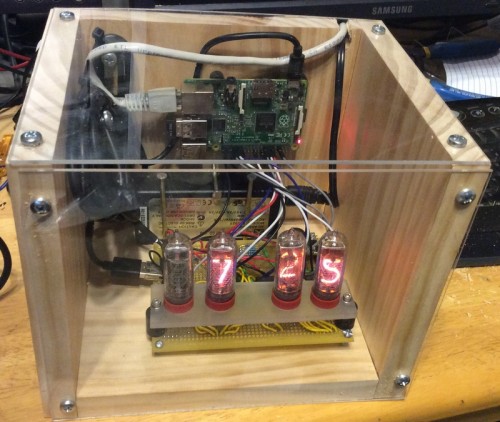
Once I had the program working, it was easy to test all the chips and Nixie Tubes. Everything worked, except one tube – the 3 and the 9 would light up at the same time. So I used this for the first digit for the hours, since that only ever needs to show 1.
The Program:
When the Raspberry Pi starts up, it automatically starts my clock program.
I wrote the clock program in C using the geany editor.
When the program starts, first it sets all the digital pins to OUTPUT and LOW to make sure everything is off.
Then I turn on pin 0, which turns on the high voltage power supply using a transistor.
Then I test the clock, which makes the hours show 1 to 12, and minutes 0-59.
Then I start the loop. Once every second I do the following:
Ask the computer the time (if it is connected to the internet, it will always show the right time).
The hours come back as a number between 1 and 23, so if the hour is bigger than 12, I subtract 12 from it.
Then I break out the hour into 2 digits, and the minutes into 2 digits. The first digit is the quotient of the hour divided by 10. The second digit it the remainder of the hour divided by 10. Then I do the same for the minutes.
For each number, I have to convert it into binary (for example 7 is 0111 in binary). Each number has up to 4 wires, each wire is for a binary digit. If the digit is 0 the pin/wire is set to LOW, if it is a 1 it is set to HIGH. So for the number 7 the wires are LOW, HIGH, HIGH, HIGH.
These wires are soldered to the driver chip. The chip has 10 switches in it, one for each number in the Nixie Tubes. These switches are connected to the chips with yellow wires. The chips look at the 4 wires to see which binary number it is, and then switches on the correct light in the Nixie Tube.
Leave a Reply
You must be logged in to post a comment.